Beam calculations become much easier when you separate three questions: what loads create, how the cross-section resists them, and how the material stiffness turns moment into curvature.
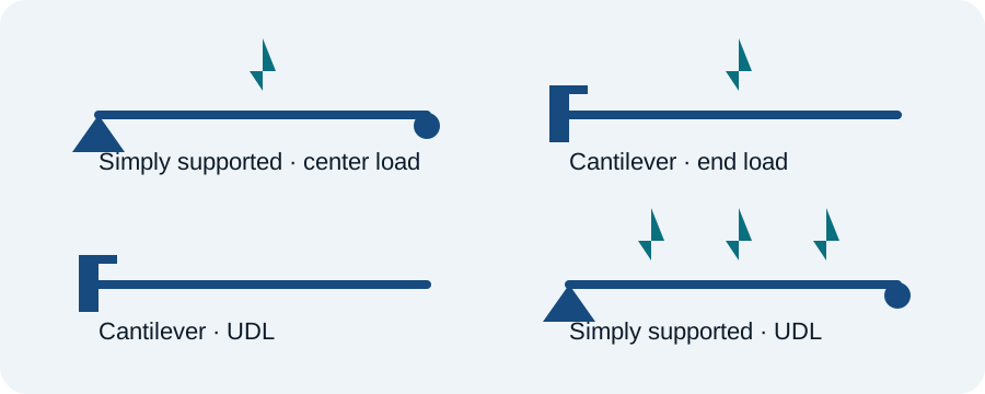
Start with the free-body diagram
Before choosing a deflection formula, identify supports, load positions and load distribution. A cantilever, a pin–roller beam and a fixed–fixed beam can carry the same external force yet develop very different moments and deflections.
Bending stress follows moment and section geometry
For elastic bending, nominal normal stress is commonly written as σ = Mc/I. The maximum magnitude occurs at the extreme fiber, where c is largest. Increasing section depth can raise I dramatically, which is why geometry often improves bending performance more efficiently than simply changing material.
Deflection depends strongly on span
Many common beam deflection equations contain L cubed or L to the fourth power. A small increase in span can therefore increase deflection much more than intuition based only on load would suggest.
Use E and I for stiffness
Elastic modulus E describes material stiffness; second moment of area I describes geometric resistance to bending about a chosen axis. The product EI is the flexural rigidity used throughout elementary beam theory.
Know when simple beam theory stops being enough
Short/deep beams can have meaningful shear deflection. Thin open sections can twist or buckle. Large deflection changes the geometry. Stress concentrations near holes, shoulders and load introduction regions are not captured by nominal beam formulas.
Practical workflow
Sketch the load path, calculate reactions and moment, determine section properties, estimate stress and deflection, then check stability, fatigue, connections and local features. Use the calculator to explore early concepts before moving to more detailed analysis.
Machine-design verification
Check the full load spectrum, fatigue, lubrication, material data, environment, manufacturing variation and the relevant machine-element standard before release.