CNC machining removes material with real cutting tools. The shape and reach of those tools should influence the CAD model long before a CAM programmer sees it.
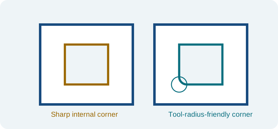
Internal corners need radius
A rotating end mill cannot create a perfectly sharp internal vertical corner. Specify an internal radius compatible with a reasonably sized cutter. Larger radii usually allow stiffer tools, higher feed rates and better surface finish.
Avoid unnecessarily deep narrow cavities
As tool reach increases relative to diameter, stiffness falls and chatter risk rises. A deep pocket with vertical walls may require long-reach tooling, reduced feeds and multiple setups. Open access or stepped geometry can dramatically simplify machining.
Design holes around standard tools
Standard drill sizes and realistic depth-to-diameter ratios are cheaper than exotic deep micro-holes. If the bottom shape matters, remember a drilled blind hole does not naturally end in a flat floor unless another operation creates it.
Tolerance follows function
General machining can hold useful precision, but very tight tolerances increase inspection, tool compensation, environmental control and scrap risk. Apply tight tolerances selectively and define critical datums.
Minimize setups
Features that can be reached from the same orientation are generally simpler than geometry requiring repeated re-fixturing. Every setup introduces time and another opportunity for datum-transfer error.
Communicate finish deliberately
Do not assign a fine surface finish to every face. Distinguish sealing, bearing, cosmetic and noncritical surfaces so the machinist can focus effort where it matters.
Release verification
Validate assumptions against current material data, applicable standards, supplier capability, inspection strategy and the complete product load case.