A compression spring is not defined by rate alone. Wire diameter, mean coil diameter, active coils, free length, solid height, stress range and end conditions all interact.
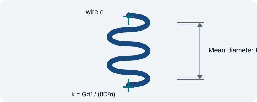
Spring rate couples material and geometry
For a round-wire helical compression spring, the familiar concept relationship is k = Gd⁴/(8D³n). Wire diameter has a fourth-power influence while mean coil diameter has a cubic influence.
Spring index affects stress and manufacturability
C = D/d. Very small indices produce tightly wound geometry with higher curvature effects and manufacturing difficulty; very large indices can create handling and stability issues. Treat index as a design-screening variable, not a quality score by itself.
Correct wire stress for curvature
The basic torsional stress is commonly corrected with a Wahl-type factor to account for direct shear and curvature. This matters more as the spring index becomes small.
Check solid height and available travel
The spring must not reach coil bind in normal operation. End coils, inactive coils and manufacturing tolerances affect solid height and usable travel, so a rate calculation alone is not enough.
Fatigue can govern repeated-use springs
For cyclic service, evaluate minimum and maximum load, mean stress, alternating stress, surface condition, residual stress, corrosion and the selected spring material. Shot peening and presetting can be relevant depending on duty.
Stability and guidance matter
Long slender compression springs can buckle. A guide rod, guide tube or larger diameter can improve stability, but friction and assembly constraints then enter the design.
Machine-design verification
Check the full load spectrum, fatigue, lubrication, material data, environment, manufacturing variation and the relevant machine-element standard before release.