FDM builds a part as roads of extruded polymer stacked layer by layer. That manufacturing direction gives the part freedoms—and limitations—that are different from injection molding or machining.
Orientation is a structural decision
Layer-to-layer strength is often lower than strength along deposited roads. Orient load paths so critical tensile stress does not simply pull layers apart. Orientation also controls support, surface quality and dimensional behavior.
Walls and nozzles interact
Thin walls should be designed with the intended nozzle and extrusion width in mind. A wall that does not map cleanly to perimeters may be approximated differently by the slicer. Preview the actual toolpath before treating nominal CAD thickness as guaranteed.
Holes often print undersize
Circular holes, especially horizontal ones, can deviate from CAD due to extrusion shape, shrinkage and layer stair-stepping. Critical holes may need compensation, drilling or reaming after printing.
Support leaves evidence
Down-facing surfaces over support usually have different roughness and dimensional accuracy than upward or vertical surfaces. Design self-supporting angles, split parts or sacrificial features where surface quality matters.
Assembly needs clearance
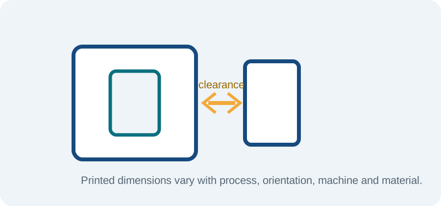
Printed mating parts require process- and machine-specific clearance. Build a small coupon or fit gauge for important assemblies instead of relying on one universal number.
Use additive strengths
FDM is excellent for integrated channels, low-volume fixtures, ergonomic forms and fast iteration. Do not copy an injection-molded part blindly; redesign around the additive process when possible.
Additive-manufacturing verification
Validate clearances, orientation, minimum features and material behavior on the actual machine/process; use the relevant ISO/ASTM additive-manufacturing guidance where applicable.