Position is one of the most useful GD&T controls for locating features such as holes and pins relative to a datum reference frame.
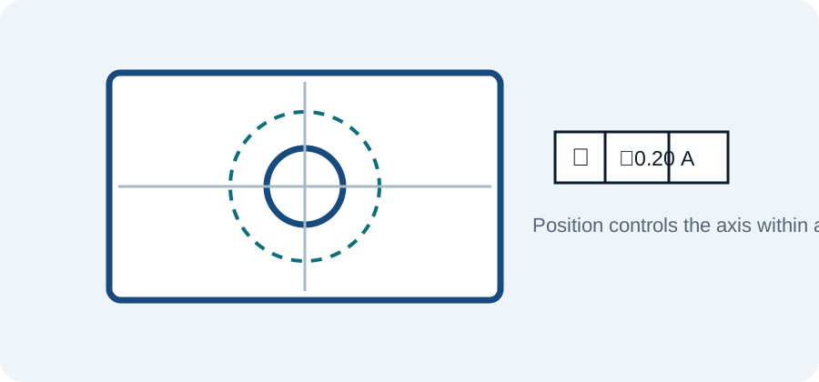
The tolerance zone
For a cylindrical feature such as a hole, position commonly creates a cylindrical tolerance zone around the theoretically exact basic location. The feature axis must remain within that zone subject to the stated modifiers.
Basic dimensions
Basic dimensions define the theoretically exact location or orientation associated with a geometric control. They are not ± tolerances themselves; the feature control frame supplies the allowed geometric variation.
Why position works well for bolt patterns
Assembly usually cares whether fasteners can pass through mating holes, not whether X and Y dimensions independently fall inside square tolerance boxes. Position expresses that radial functional relationship more naturally.
Material condition modifiers
MMC and LMC can change how geometric tolerance interacts with feature size. At MMC, bonus tolerance may become available as the actual feature departs from its maximum-material size. Learn this carefully before using it on production drawings.
Datum sequence matters
A position requirement is only as meaningful as its datum reference frame. Choose datums that represent how the part locates in assembly or inspection.
Check the whole stack
A generous position tolerance on one part may still fail in assembly if the mating pattern has no complementary allowance. Analyze both sides together, including fastener size and any floating or fixed-fastener condition.
Drawing & GPS verification
Confirm the drawing standard named on the product documentation and use the current applicable ISO GPS or ASME Y14.5 requirements.