A sheet-metal part is not just a thin solid. The manufacturing sequence—cut, punch, bend, form, weld—determines which geometries are robust and economical.
Use a consistent material/thickness system
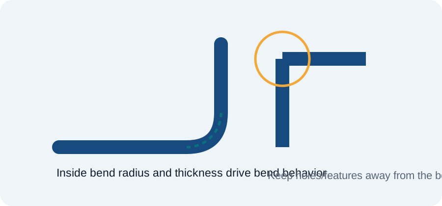
Build the model with the actual sheet thickness and a defined bend rule. Mixing arbitrary inside radii or manually modeling each bend makes flat-pattern prediction less reliable.
Bend radius and tooling
Minimum bend radius depends on material, temper, thickness, grain direction and forming method. Use your fabricator’s tooling capability rather than assuming the smallest radius CAD allows.
Keep holes away from bends
A hole too close to a bend can distort as the flange forms. Distance requirements vary with process and material; when space is tight, ask whether the hole should be made after bending or moved farther from the bend zone.
Add bend relief where needed
At the end of a bend, material must flow. Relief slots or notches can prevent tearing, bulging and unpredictable corner deformation. The exact relief geometry should match the forming process.
Think about tool access
A flange may collide with press-brake tooling during a later bend. Sequence matters. Deep channels, return flanges and closely spaced bends should be reviewed with the fabricator before release.
Dimension the formed part functionally
Do not over-constrain both flat and formed dimensions unless process control requires it. Specify the features that matter in the assembled state and identify inspection datums that can actually be accessed.
Release verification
Validate assumptions against current material data, applicable standards, supplier capability, inspection strategy and the complete product load case.