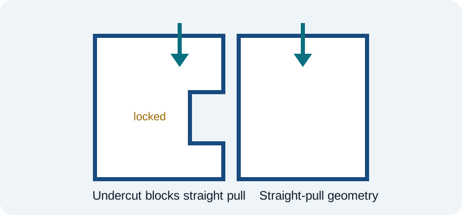
An undercut is geometry that prevents a part from moving freely in the chosen mold-opening direction. It does not automatically make a design impossible, but it changes the tooling conversation.
Recognize the pull direction first
You cannot identify an undercut without a defined pull direction. A feature may be an undercut in one orientation and perfectly straight-pull in another. Choose the likely mold orientation early and perform an undercut/draft analysis before detailing the part.
Common solutions
Toolmakers may solve undercuts with slides, lifters, collapsible cores, removable inserts, split cavities or other mechanisms. Each solution adds some combination of tool size, moving components, maintenance, cycle time and cost.
Strippable undercuts
Some flexible polymers can elastically deform over a shallow rounded undercut during ejection. Whether stripping is sensible depends on material strain capability, feature depth, local wall thickness, radii, temperature at ejection and repetition. Treat it as an engineering calculation plus molding trial, not a blanket permission to add hooks.
Part redesign can be cheaper
Before committing to a side action, ask whether a slot, opening, snap orientation, assembly split or change in parting line can convert the feature to straight pull. A small geometry change can remove a large tooling mechanism.
Hidden tooling consequences
Undercuts can also constrain gate location, ejector placement, cooling channels and parting-line strategy. If multiple slides approach the same region, tool robustness can degrade quickly.
DFM review question
For every undercut, document: what functional requirement creates it, how much undercut is required, what material deformation is acceptable, and what tooling concept is expected. That makes cost/benefit decisions explicit.
Injection-molding verification
Confirm resin-grade data, mold construction, texture/draft requirements, shrinkage assumptions and the selected molder's capability.