Bosses concentrate multiple engineering functions into a small region: fastening, positioning, stiffness and load transfer. That also makes them a common source of DFM problems.
Start from the fastening function
Define what the boss must do before dimensioning it. A self-tapping screw boss, heat-set insert boss, locating boss and through-bolt tower have different wall, diameter and support requirements.
Keep the boss from becoming a solid lump
A boss should usually be cored rather than solid. Its wall thickness is commonly kept in the same general range as a rib relative to the nominal wall, then tuned for the resin and fastening method. Thick boss walls and thick boss-to-wall intersections are frequent causes of sink.
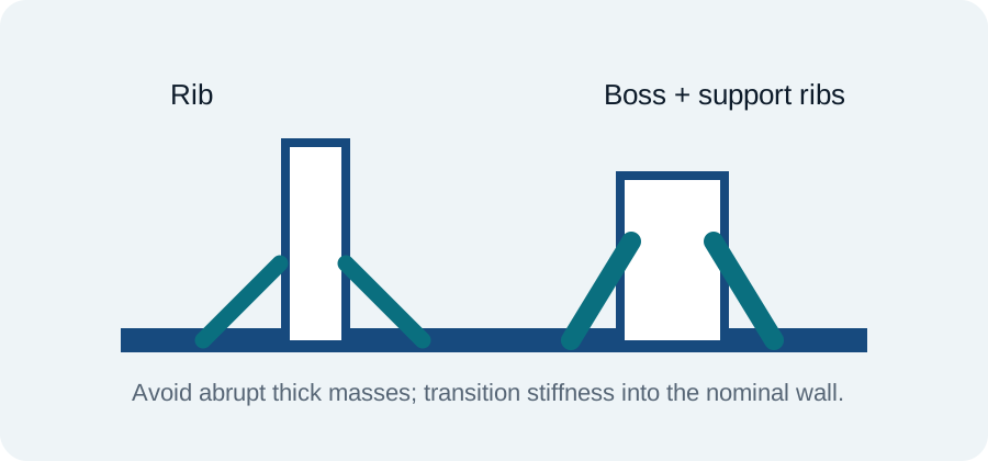
Support with ribs and gussets
If the boss is tall or loaded laterally, use ribs or gussets to carry the load instead of simply increasing the entire boss wall. This can improve stiffness while keeping the thermal mass under control.
Design around the screw or insert
For thread-forming screws, follow the fastener supplier’s pilot-hole and boss-diameter guidance rather than applying a generic percentage. For inserts, check insertion process, heat path, knurl geometry, edge distance and the remaining plastic around the insert.
Draft, fillets and tool steel
Boss OD and ID surfaces may need draft depending on how they are formed and ejected. Avoid knife-edge steel between a boss hole and nearby features. Add reasonable root radii and confirm that the tool can cool the boss region.
Assembly tolerance
A boss rarely works alone. Check hole-position tolerance, mating-part clearance, screw access, driver clearance and stack-up. A perfectly molded boss can still make assembly difficult if the mating hole pattern has no positional allowance.
Injection-molding verification
Confirm resin-grade data, mold construction, texture/draft requirements, shrinkage assumptions and the selected molder's capability.