A snap fit is a temporary elastic deformation used to create a mechanical connection without a separate fastener. The geometry looks simple, but reliability depends on controlling strain and load path.
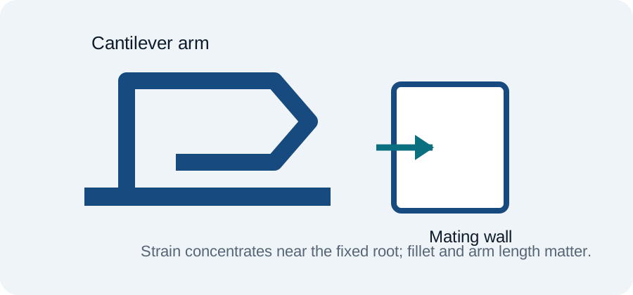
The basic cantilever model
Many plastic snaps behave approximately like cantilever beams. During assembly the hook deflects, storing elastic energy; after passing the mating feature it recovers and creates retention. Beam length, thickness, taper and material modulus strongly affect the required force and strain.
Strain is usually the limiting quantity
A snap can be strong in a static strength calculation yet fail after repeated use because local strain exceeds the material’s allowable range. Sharp root corners make this worse. Long compliant arms and generous root radii usually reduce peak strain.
Assembly force versus retention
More hook engagement increases retention, but it can also increase assembly force and overstress the arm. Separate the ramp angle used during assembly from the retaining face angle so the two behaviors can be tuned independently.
Account for creep
Thermoplastics under sustained deflection can relax over time. Avoid designing a reusable snap that remains heavily bent in the assembled condition. Ideally the arm returns close to its neutral position after engagement.
Injection-molding considerations
Add draft where required, avoid thick hook roots, consider the parting line and ejector direction, and check whether the hook itself creates an undercut. Sometimes a slot or open window lets the snap be produced with straight-pull tooling.
Prototype the real material behavior
Printed prototypes are useful for checking access and assembly sequence, but an FDM or resin print rarely reproduces the exact flexural behavior of the final molded polymer. Use them as geometric prototypes, then validate with representative material and process.
Release verification
Validate assumptions against current material data, applicable standards, supplier capability, inspection strategy and the complete product load case.